Axial Ventilation Fans: Working Principle, Types, Selection and Standards
An axial ventilation fan moves air parallel to the axis its blades rotate around: aerofoil blades on a central hub draw air straight through the impeller, delivering high airflow at low pressure. That flow-first character makes them the workhorse of industrial ventilation, smoke extraction, tunnels, car parks and process cooling.
What Is an Axial Ventilation Fan?
An axial ventilation fan is a fan whose impeller draws air in and discharges it along the same axis as its shaft; a centrifugal fan instead turns the airstream roughly 90 degrees and pressurises it by radial acceleration. Rotating aerofoil blades give large volume flow, a few hundred m³/h for a panel fan up to a million m³/h and beyond for main tunnel and mine fans, against modest static pressure: tens of pascals to roughly 2,000 Pa for cased high-performance designs.
How an Axial Fan Works
The impeller carries fixed or adjustable-pitch blades on a hub, usually mounted directly on the motor shaft. Each blade generates lift like an aircraft wing, accelerating air axially; the stream leaves with rotational swirl, wasted energy unless recovered. Four parameters dominate:
- Blade pitch angle: steeper pitch moves more air and absorbs more power; many impellers adjust at standstill, one casing covering a wide duty band.
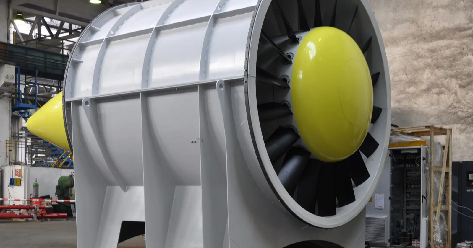
- Hub-to-tip ratio: roughly 0.3 to 0.5 for tube-axial and 0.6 to 0.8 for vane-axial fans; the larger hub shifts blading toward higher pressure at lower flow.
- Tip speed and tip clearance: pressure capability rises with tip speed, but so does noise; the tip gap must stay small, since leakage erodes pressure and efficiency.
- Blade solidity and form: more or wider blades (higher solidity) raise pressure; aerofoil sections beat flat plates, and backward-skewed “sickle” profiles cut tonal noise.
In vane-axial fans, stationary guide vanes convert that swirl into static pressure, worth several efficiency points over a tube-axial equivalent.
Types of Axial Ventilation Fans
Beyond the usual propeller, tube-axial, vane-axial trio, real projects specify these configurations.
| Type | Construction | Typical static pressure | Typical duty |
|---|---|---|---|
| Wall / panel (propeller) fan | Impeller in a plate or short ring | Up to roughly 100–150 Pa | Through-wall exhaust for workshops (wall-mounted axial fans) |
| Tube-axial (inline duct) fan | Impeller in a cylindrical casing | Roughly 150–600 Pa | Ducted supply and extract, process exhaust, fresh-air supply units |
| Vane-axial fan | Cased impeller with guide vanes | Up to roughly 2,000 Pa | Higher-resistance ducts, tunnels, mines, marine ventilation |
| Bifurcated axial fan | Motor outside the airstream in a split casing | Similar to tube-axial | Hot, humid or greasy air: kitchen and process exhaust |
| Jet (impulse) fan | Unducted impulse unit | Thrust-rated in newtons (ISO 13350) | Ductless car-park and tunnel ventilation and smoke control |
| Roof axial fan | Vertical- or horizontal-discharge cowled unit | Low to moderate | Hall and warehouse extract; stairwell and shaft ventilation |
Where one impeller cannot meet the pressure, two can run in contra-rotating series; the second stage also recovers the first’s swirl, so the pair typically gives 2.2 to 2.5 times single-stage pressure. Series otherwise roughly doubles pressure and parallel doubles flow, the real gain set by the system curve.
Axial vs Centrifugal Fan: Which One?
System resistance decides; the table shows typical behaviour.
| Criterion | Axial fan | Centrifugal fan |
|---|---|---|
| Airflow direction | Straight through, parallel to shaft | Turned ~90°, radial discharge |
| Static pressure | Low to moderate (up to ~2,000 Pa typical) | Moderate to high (several kPa achievable) |
| Peak total efficiency | Up to roughly 85% (aerofoil vane-axial) | Comparable (backward-curved aerofoil) |
| Footprint | Compact, mounts inline in duct or wall | Larger; needs scroll casing and transitions |
| Noise character | Blade-pass tone, rises steeply with tip speed | Broader-band, easier to attenuate at high pressure |
| Cost per m³/h | Lower | Higher |
| Best suited to | Low-resistance, high-volume ventilation and smoke extract | High-resistance systems: filter banks, long ducts, process air |
Rule of thumb: open areas and short duct runs favour axial on cost, footprint and energy; filters, heat-recovery cells and long ductwork favour a centrifugal or plug fan, with vane-axial in the overlap.
Performance: Fan Curve, Fan Laws, Efficiency and Noise
Pressure terms
- Static pressure (Pa): the system resistance the fan must overcome; strictly (EN ISO 5801), fan total pressure minus outlet dynamic pressure, so check the test basis between datasheets.
- Dynamic (velocity) pressure: the airstream’s kinetic energy, ρv²/2.
- Total pressure: the sum of the two; published curves state which basis applies.
The fan curve
A fan curve plots pressure against flow at fixed speed; the duct network’s system curve rises roughly with flow squared, and the intersection is the operating point. Axial curves carry a stall region, a dip left of the pressure peak where flow separates from the blades, bringing pulsation and blade fatigue; pushed further left, flow can break into unstable reversal, surge. Select right of the dip, near the best efficiency point (BEP); oversized margins throttle fans into stall.
The fan laws (affinity laws)
For a given fan and air density:
- Flow: Q₂ = Q₁ × (N₂/N₁)
- Pressure: p₂ = p₁ × (N₂/N₁)²
- Absorbed power: P₂ = P₁ × (N₂/N₁)³
The cube law is the economics of ventilation: running 20% slower roughly halves absorbed power (0.8³ ≈ 0.51), so demand-based speed control pays back quickly. Flow also scales with diameter cubed and pressure with diameter squared: a larger, slower impeller is usually quieter and more efficient at the same duty.
Efficiency, ISO 12759 and ErP
Efficiency is air power over input power, quoted static or total; never compare across bases. Typical peak total efficiencies: propeller fans roughly 45–60%, tube-axial 60–75%, aerofoil vane-axial up to about 85%. EU Ecodesign Regulation 327/2011 sets minimum efficiency grades (N-values) via a target-efficiency formula for fans driven by motors with an electric input power of 125 W to 500 kW; the 2015 tier for axial fans is N40 static or N58 total, measured per EN ISO 5801. The ISO 12759 series adds the FMEG classification for fan-and-motor packages; specific fan power (kW per m³/s) is the most honest whole-system comparator.
Noise
Distinguish sound power (tested to ISO 13347 or AMCA 300) from sound pressure (dBA at a stated distance, installation-dependent). Axial noise is set by tip speed and the blade-pass tone (blade count × revolutions per second). Remedies: a larger fan run slower, sickle blades, tight tip clearance, staying clear of stall, and silencers; request octave-band data, not one dBA figure.
Motors and Drives
Almost all modern axial fans are direct drive, impeller on the motor shaft: no transmission losses, no belt maintenance. Belt drive survives in legacy roof and agricultural units, buying a cheap speed ratio for a few percent drive loss and belt upkeep.
AC induction motors (IE3/IE4 per IEC 60034-30-1) with a variable frequency drive (VFD) are standard for larger fans; specify inverter-rated insulation and lock out resonance bands. EC motors integrate the drive electronics, stay efficient at part load and accept 0–10 V or Modbus control directly: the default for smaller fans and demand-controlled ventilation.
Blade Design, Materials and CFD
Impeller blades are commonly cast or extruded aluminium alloy for general ventilation, steel where smoke-duty temperature classes demand it, and glass-reinforced composites for humid or corrosive air; in ATEX builds, EN 14986 restricts impeller and casing material pairings to limit friction sparking.
Blade profile, skew and hub geometry are now developed with computational fluid dynamics (CFD), trading pressure, efficiency and noise before a prototype is cut. CFD also works at system level: car-park jet-fan layouts are routinely verified with CFD analysis of velocity, CO and smoke distribution.
Where Axial Ventilation Fans Are Used
Industrial, commercial and general ventilation
Wall fans, inline duct fans and roof units ventilate factories, warehouses and plant rooms; sizing starts from air changes (airflow m³/h = room volume × air changes per hour), checked against heat load and code. Compact axials cool electronics and vehicle radiators; larger units serve data-centre heat rejection.
Car parks, tunnels and metro
Ceiling-mounted jet fans replace car-park ductwork, running on CO-sensor demand and stepping to full speed for smoke control; see our car park ventilation and fire safety guide for layout logic. Road tunnels and metro systems use larger reversible tunnel fans; main mine ventilation and safety-qualified nuclear-plant duties sit at the heavy end of the family.
Smoke and heat exhaust: EN 12101-3
Powered smoke and heat exhaust ventilators must be certified to EN 12101-3; the principal temperature-time classes run F200 (200 °C, 120 min), F300 (300 °C, 60 min), F400 (400 °C, 90 or 120 min), F600 (600 °C, 60 min) and F842 (842 °C, 30 min). Certification sits under the Construction Products Regulation, so request the declaration of performance; a dual-duty smoke exhaust fan must carry the class for the emergency case.
ATEX and explosion-hazard areas
Fans for explosive atmospheres fall under ATEX 2014/34/EU: gas zones 1/2 and dust zones 21/22 map to equipment categories 2 and 3; EN 14986 governs spark-resistant material pairings, tip clearances and Ex motors. EN 14986 does not cover Category 1, so fans are effectively unavailable for zones 0 and 20: keep the fan outside them by design, and state zone, group and temperature class at enquiry.
Cooling, process and agricultural air
Axial fans also sweep condensers, dry coolers and cooling towers, and handle extract around heat-recovery and air-handling plant; livestock housing, greenhouses and grain stores are classic propeller territory: huge volumes at near-free air, corrosion-protected against humid, ammonia-laden atmospheres.
Axial Fan Selection Checklist
Work through this list before requesting quotations; it prevents the costliest specification errors.
- Airflow in m³/h and its basis: air changes, heat load or code.
- Static pressure at that airflow, from the actual duct layout, margined sensibly rather than oversized into stall.
- Air density corrections for temperature, humidity and altitude (curves assume standard air).
- Operating temperature, plus the EN 12101-3 class for any smoke duty.
- ATEX zone and category, gas/dust group and temperature class, where applicable.
- Efficiency and compliance: ErP 327/2011 grade, FMEG per ISO 12759, motor IE class, static or total basis.
- Noise limit in dBA at a defined position, with octave-band sound power data.
- Drive and speed control: direct or belt, VFD or EC, minimum turndown, resonance speeds to lock out.
- Mounting and accessories: orientation, guards, dampers, silencers, flexible connectors, flanges.
- Environment and build: IP rating, insulation class, blade and casing materials for corrosive or coastal air.
- Test basis and documentation: EN ISO 5801 performance, ISO 13347 sound, curves, declarations of performance, spares.
If a point is open, a short enquiry with the duty point via our contact page usually settles selection in one round.
Installation and Maintenance
Axial fans are inlet-sensitive: give the impeller a straight duct section or a bellmouth, since a hard-up elbow creates pre-swirl that shifts the curve and raises noise. Fit flexible connectors and anti-vibration mounts, and verify rotation at commissioning; a reversed fan still moves some air, hiding the fault.
- Clean blades on a schedule; deposits unbalance the impeller. Fans are commonly balanced to G6.3 per ISO 21940-11 (BV-3 in the fan-specific ISO 14694).
- Check tip clearance and casing condition; a widened gap quietly degrades pressure and efficiency.
- Trend bearing temperature, vibration and motor current against nameplate; rising vibration is the earliest cheap warning.
- Test smoke-duty fans under the fire strategy; an emergency fan must never be found failed in a fire.
- Investigate low-frequency pulsation immediately; it usually means stall, and the fix is on the system side, not in the fan.
FAQ: Axial Ventilation Fans
What is an axial ventilation fan used for?
Any duty moving large volumes against modest resistance: industrial and building ventilation, roof and wall extract, car parks and tunnels, smoke exhaust, cooling towers, electronics and agriculture.
Are axial fans good for ventilation?
Yes: they are the default for most general ventilation, giving the most airflow per unit of cost, space and energy. Just confirm the duty lands right of the stall region.
What is the difference between an axial fan and a centrifugal fan?
An axial fan moves air parallel to its shaft and favours high flow at low pressure; a centrifugal fan turns the air about 90 degrees to build the higher pressures that filtered, long-duct systems need.
What is the difference between an axial fan and a blower?
In HVAC usage a “blower” usually means a centrifugal fan built for higher pressure at lower flow, as in an air handling unit. Both are formally fans; markedly higher pressure ratios make a compressor.
Can an axial fan develop high static pressure?
Within limits. Guide-vane and contra-rotating designs reach roughly 2,000 Pa or more, covering most ducted ventilation; beyond that, centrifugal fans are usually the better tool.
Are axial fans noisy?
They can be at high tip speeds, with a distinct blade-pass tone; a larger fan run slower, sickle blades and silencers keep installations within typical dBA limits.
Which standards apply to axial ventilation fans?
Performance: EN ISO 5801 / ANSI/AMCA 210. Sound: ISO 13347 / AMCA 300. Efficiency: ISO 12759 with EU 327/2011. Smoke duty: EN 12101-3. Jet fans: ISO 13350. Explosive atmospheres: ATEX 2014/34/EU with EN 14986.
Venturka manufactures and exports axial, smoke-exhaust and jet fans across the Gulf, Middle East, Balkans and the EU: browse the product range or send duty points for a selection proposal.
Header photo: tube-axial fan for a wind tunnel by TCF Vzduchotechnika s.r.o., CC BY-SA 4.0, via Wikimedia Commons.